

Discussion on the Method of Using Illuminance for Calculating Lumen Output in Cone-Shaped Stage Ligh
2023-11-21 Post By: Longmangroup
Discussion on the Method of Using Illuminance for Calculating Lumen Output in ConeShaped Stage Lighting and Landscape Lighting FixturesDiscussion on the Method of Using Illuminance for Calculating Lumen Output in Cone-Shaped Stage Lighting and Landscape Lighting Fixtures
Comparing illuminance at a fixed distance has become a widely adopted, simple, and effective method for comparing the brightness of two stage and landscape lighting fixtures. However, when dealing with fixtures with slightly different angles, comparing axial illuminance does not necessarily explain the difference in lumen output. For example, for a 15-degree fixture, axial illuminance might be 100Lx, and for a 20-degree fixture, it might be 90Lx. Which fixture has a higher lumen output? This can be challenging for regular homeowners and designers. Testing a single luminaire's IES is not only difficult but also incurs high costs and takes a considerable amount of time.
By collecting a bit more illuminance data, we can calculate the lumens of the luminaire, similar to how an integrating sphere works. This is especially applicable to cone-shaped light fixtures with smooth transitioning light distribution curves. This article emphasizes the straightforward calculation of lumens for such fixtures.
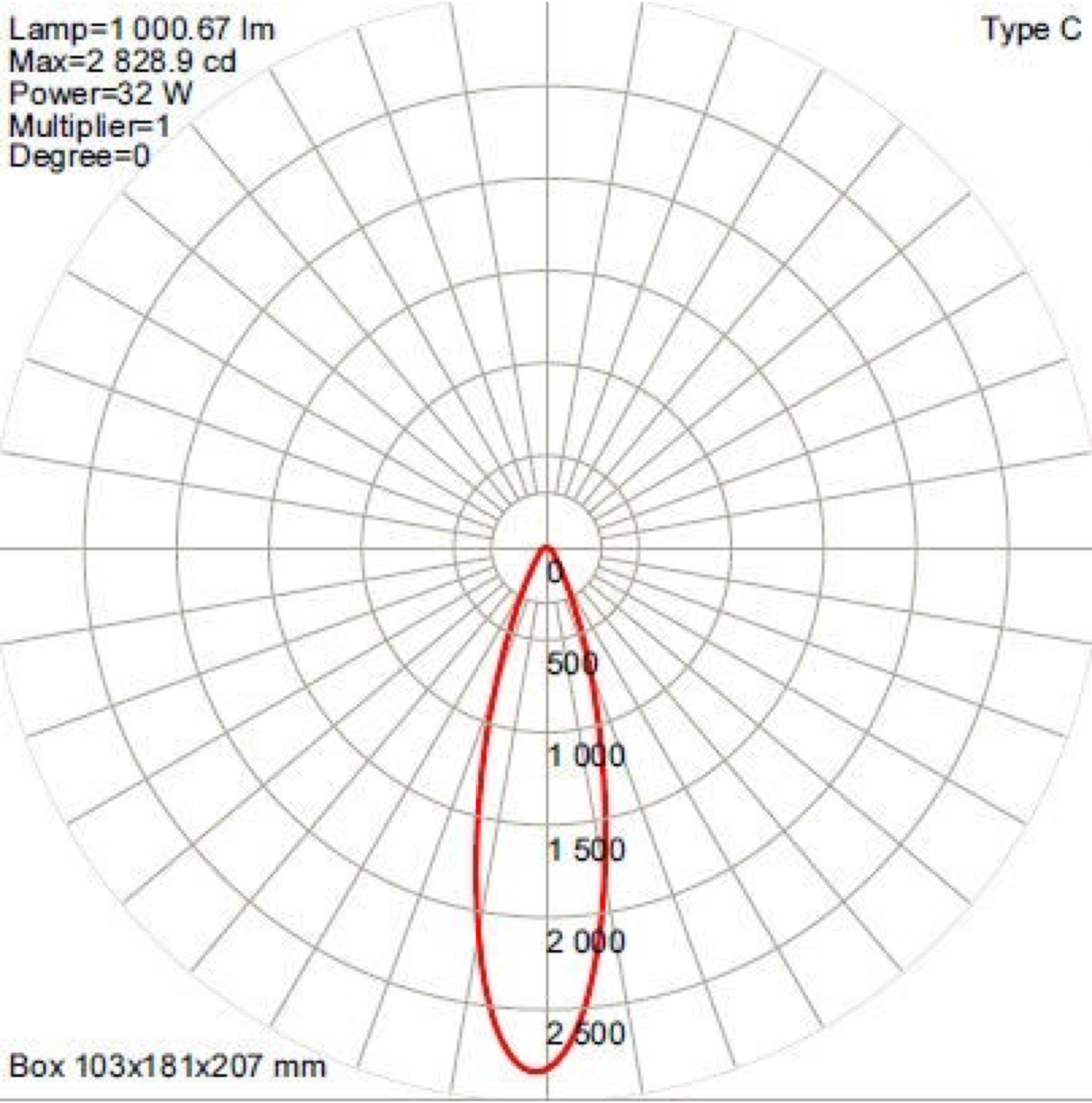
This type of cone-shaped light distribution meets the following conditions: the light source is an approximate point source, the primary light distribution is Lambertian with a 120-degree (50% beam angle) spread, the chip is rectangular, approximating a point, and the secondary light distribution lens surface is either frosted or honeycomb for optimal performance. The light surface can also be approximated, and the illuminance follows a negative quadratic decay with distance.
Generally, cone-shaped light distributions have two angular parameters: the beam angle and the spot angle. The beam angle is the axial section angle formed by the 50% light intensity line, while the spot angle is the axial section angle formed by the 10% light intensity line. Typically, the latter is about twice the former.
The method proposed in this paper calculates the total lumens within the range corresponding to the spot angle, i.e., all lumens within the 10% light intensity.
The principle underlying this method is that lumens are the product of illuminance and area. The total lumens on a sufficiently small area are the product of illuminance and area. Therefore, the lumens of the spot are the integral of illuminance over the area in all directions. Considering the circular nature of the spot, with nearly equal illuminance in the circumferential direction, it can be calculated as the integral of illuminance on the radius length direction on a micro ring. To illustrate this more clearly, a coordinate system XOZ is established (here, Z is only offset from the subsequent function references and does not involve three-dimensional coordinates), where O is the center of the spot.
The spot's strongest illuminance point is generally considered to coincide with the center O.
The illuminance y obtained on a circular ring of the same radius is basically consistent.
The illuminance y at any position is a function of x. After testing, a Gaussian fit is performed to determine the illuminance collection method.
Choose an axial direction suitable for the distance to shine the luminaire, forming a spot perpendicular to the axial direction.
Adjust the spot to have similar or close illuminance at the same distance from the center.
Use a grid for the spot, at least an 11*11=121 point array grid, finer is better.
The collected points must cover all areas within the 10% light intensity, with a few points allowed outside the 10% light intensity, which can also be used for calculation and fitting, with minimal impact on the results.
The integration reasoning process:
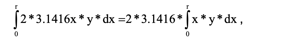
Select a circular ring with a radius x, with an extremely thin thickness, as a micro-element increment dx. The area of this circular ring is 2*3.1416x*dx, and the illuminance at this circular ring is y. The lumens on this circular ring are then calculated(2*3.1416x*dx)*(y),Perform a definite integral of the given quantity within the effective radius distance of the spot. The lower limit of integration is 0, and the upper limit of integration is the radius length r corresponding to the location where the illuminance is 10% of the maximum at the spot..
Data Processing
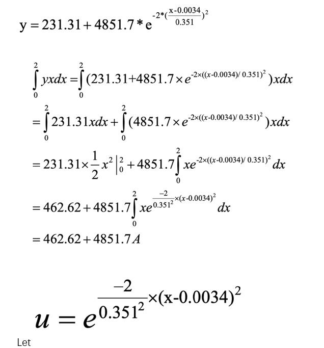
Collect values, take the average of the four symmetrically centered points as the illuminance at that coordinate (this step can further reduce system errors). Then, use Origin software to plot the "Distance from the Center Point vs. Illuminance" relationship and perform Gaussian fitting to obtain the standard fitting formula.
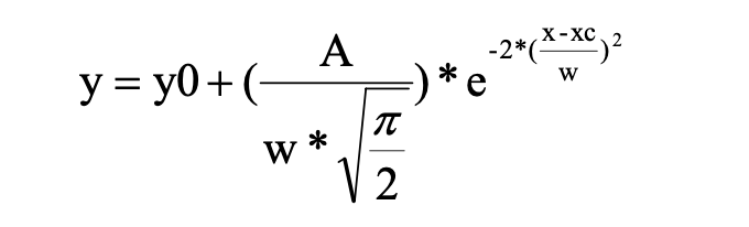
There are constants: y0, xc, w, A. In addition, the unknown x is the distance from point O, y is the illumination at the x distance, and the required lumens value is obtained by integrating 2*3.1416x*y*dx.
Among them, r is the spot radius, which is the upper limit of the integral of the definite integral. The compound derivation formula needs to be used here: (eu(x)) '=eu(x) ·u(x)' to calculate the accurate value.
For example: Suppose a lamp projects a light spot with a radius of 2 meters on the wall. After data collection and fitting, After that, get
The compound derivative formula used to derive u:
Get:
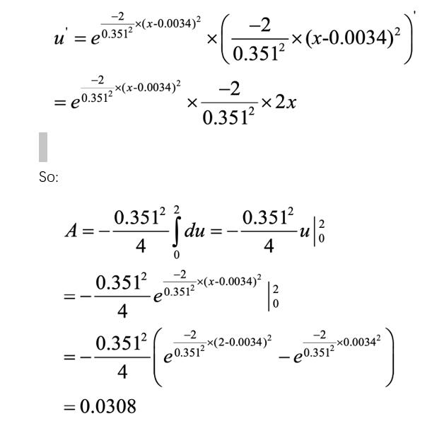
So:
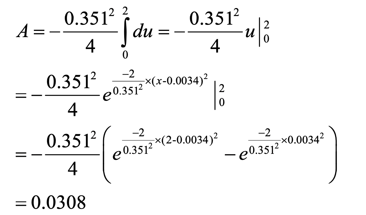
Therefore, original points = 462.62 + 4851.7 × 0.0308 = 612
The number of lumens of the lamp = 2*3.1416*612=3845lm.
Calculation completed.
The method of calculating lumens using illuminance proposed by this method is suitable for calculating the lumen number of lamps without large instruments, integrating spheres and darkrooms, especially when comparing a large axial light intensity at a small angle and a small axial light at a large angle. The lumen output of strong lamps is very useful, suitable for identifying and purchasing products, and can also be used to evaluate lamps during on-site lamp testing.
Note:
Author Becken Han, technical director of Guangzhou Longman Optoelectronics, chief designer of Longman Global Design Support Center
Member of the National Senior Lighting Designers Alumni Association, professional member of the Chinese Lighting Designers Association CLDA
IALD International Association of Lighting Designers Affiliate member
Guangzhou Longman Optoelectronics uses nonlinear optical imaging technology as a technology carrier to develop a variety of stage performance lighting and architectural landscape lighting products, including water-based water dancing lights, waterfront rhythmic water dancing lights, heart of the ocean water dancing lights, and sunset reflections on the river. Dancing lanterns, sacred fire lanterns for good luck, tree shadow lanterns with the bright moon, spring, summer, autumn and winter grass dance lanterns, spring flowers and autumn flowers dance lanterns, clouds rolling and relaxing clouds dance lanterns, gentle breeze and drizzle rain dance lanterns, rainbow-like imaging lanterns, golden light showing imaging Stage special effects lamps such as lights and integrated with dynamic light and shadow provide new design elements for stage lighting designers and landscape lighting designers.
Guangzhou Longman Optoelectronics will continue to refine more traditional Chinese cultural elements into specific images, providing fresh elements for more architectural and landscape lighting with dramatic effects.
To learn about Longman Optoelectronics’ professional stage lighting products, please visit website: www.longmanlight.com
To learn about Longman Optoelectronics’ professional landscape and arc lighting products, please visit website: www.ledmewish.com